Front Teeth Dental Implants — An Anterior Case Walk-Through from Our Lab


🕢 [ Udfyld formularen, så svarer vi inden for 30 minutter! ].
ASD Dental Lab is a full-service dental laboratory based in Shenzhen and Huizhou, founded in 2012. We make restorations — we do not provide any clinical care.
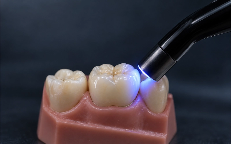
The focus here is a single-tooth front teeth dental implants restoration in the maxillary esthetic zone.
1. Patient Situation (as described in the clinician’s referral)
- Adult patient, non-smoker, no systemic concerns flagged on the referral form.
- UR1 was lost to trauma years ago; the gap had been held by a resin-bonded bridge since then. The clinician asked us to keep that record in the file because it affected how the soft tissue had settled.
- A bone graft had been placed, and the implant was positioned by the surgeon. The implant was now ready for the prosthetic stage.
- The adjacent UR2 and UL1 had small composite shade mismatches. The patient’s own request to the clinician was explicit: “I want it to look like a tooth, not a crown.”
Because this is an esthetic-zone single implant, the dentist did not ask for an immediate load; the implant had already integrated and a healing component was in place when the final-crown data was sent to us. For the general framing of when loading can be moved forward, ITI consensus on implant placement and loading protocols is the common reference clinicians use.
2. The Clinician’s Requirements — Written Down, Numbered
The dentist listed seven requirements on the lab slip. We quote them below in plain language and respond to each one in Section 3, point by point. This 1-to-1 mapping is how we keep responsibility visible: your words on the left, our bench work on the right.
| # | What the clinician asked for |
| R1 | Screw retention if the access channel can land palatal; otherwise an angled screw channel; cement retention only as the last option. |
| R2 | A custom titanium base + lagdelt zirkonia-krone; keep the metal interface, keep the esthetic layer separate. |
| R3 | Build the emergence profile from the photos of the provisional/healing component — do not guess. Match the soft-tissue cuff the patient has worn in. |
| R4 | Shade: match UR2 and UL1 as seen in the clinical photos, including the mild incisal translucency the patient has in those teeth. |
| R5 | Passive fit on the model, no screw-driven seating. Verify, then verify again. |
| R6 | Clean margins, hygienic undersurface, no acute edges that trap plaque. |
| R7 | Deliver the restoration with the fixation screw bagged separately, labelled, torque left to the clinician’s system. |
Each requirement maps to a specific choice we made. We spell them out next so a technician in your chair can replay the decisions.
3. How the Lab Met Those Requirements
R1 — Retention: screw first, angled channel if the axis forces it, cement only as a fallback
We designed R1 as a screw-retained anterior crown. The intra-oral scan showed the implant axis angled slightly labial. The CAD planning placed the screw access on the cingulum, which is where screw-retained anterior restorations usually land in the published RCT data in Five-year RCT comparing cemented and screw-retained implant-supported single crowns (PMC). For the broader comparison between the two retention types, see Systematic review of screw-retained versus cement-retained fixed implant prostheses (PMC).
If the axis had been more labial we would have gone to an angled screw channel instead of cement retention — our knowledge base entry on this question is explicit about that order: screw first, angled screw channel second, cement only when the first two fail the esthetic test.
R2 — Custom titanium base + layered zirconia superstructure
A single stock abutment would not give R1 the margin position the dentist wanted. We built a custom titanium base with the margin kept 0.5 mm sub-gingival on the labial, equi-gingival on interproximal, and supra-gingival on the palatal — those three heights are not symmetric on purpose, they follow the soft-tissue scallop in the photos.
The crown on top is layered zirconia. The internal choice between zirconia and a titanium-only abutment under the esthetic zone is where soft-tissue colour can be visible through thin biotype; the comparison in Esthetic, mechanical, and biological outcomes of various implant abutments (PMC) is the one our senior designers use when the clinician does not specify.
Bonding of the zirconia to the titanium base followed the protocol our KB documents under P173/P174: masked implant interface, 50 μm alumina on the bonding surface only, MDP primer, dual-cure resin cement, gap window kept at 20–50 μm, excess cement cleaned in the gel phase. The implant interface itself was never touched by cement; that is a non-negotiable in our line.
R3 — Emergence profile from the provisional, not from guesswork
The clinician’s note was the right one here. The soft-tissue cuff a provisional has shaped over weeks is not something a technician can invent from a scan alone. We used the photographs of the healing component in situ, together with the digital impression of the gingival sulcus, to copy the width-to-emergence curve as it already existed. The design file was sent back to the clinician for a visual check before milling, exactly as our KB entry G246 describes.
Published guidance on anterior emergence design and peri-implant esthetics is in Peri-implant esthetics assessment and management (PMC).
R4 — Shade
ASD is a lab, not a chair. We do not pick shades directly from a patient. We work from what the clinician sends us:
- A cross-polarised photo of UR2 and UL1 with a shade tab in frame.
- Two shots at different light angles so we can see how the incisal translucency behaves.
- A written note of the base shade plus any modifiers.
For this case the dentist specified a warm A2 body with a slightly cooler incisal, mild halo, no visible mamelons. Our ceramist layered to that spec and shot a photo back under the same lighting conditions before glaze. Final glaze was adjusted after the clinician approved the pre-glaze photo. This loop is where single-tooth anterior cases either win or lose — the clinical photographs do most of the work, our KB entries P132/P191 cover the back-and-forth.
R5 — Passive fit on the model
Passive fit on a single-unit anterior crown is simpler than on an All-on-X bridge, but we do not skip it. On the printed model:
- The crown seats under its own weight on the implant analog.
- No rock, no lift at the margin when a probe is run around.
- The screw was finger-tightened first and visually inspected for cant; final torque is left to the clinician’s torque driver on the brand you specified.
For multi-unit anterior bridges and larger spans we add a verification jig step; the KB defines that boundary at “multiple implants, long span, or complex structure” (G250). Not applicable here, kept on the file for the record.
R6 — Margins and the hygienic undersurface
The subgingival-to-supragingival margin pattern we built in R2 is only half of this requirement. The other half is the surface finish:
- Mesial and distal interproximal contours were polished flat enough to admit floss and an interdental brush.
- The palatal cingulum was rounded; no sharp line angles.
- The occlusal / incisal path was designed for a slight disclusion in protrusion so the patient’s natural canines guide excursions — we built it to the clinician’s note.
The population-level framing on peri-implant soft-tissue and keeping the mucosa healthy is in Risk indicators and prevention of implant soft-tissue complications (PubMed) og Peri-implant diseases and conditions consensus report (PubMed).
R7 — Delivery and the fixation screw
The fixation screw was placed in a separate labelled pouch inside the main case box, cross-referenced to the case number. We do not pre-torque; torque values live in the implant manufacturer’s documentation, not in our lab. If you have asked for an original-brand screw, that is what is in the pouch; if you accepted a validated compatible component, that was noted on the order form and in our shipment list, following KB entries G239 and P168 — the clinician authorises any component substitution, not the lab.
4. The In-House Workflow Behind This Restoration
This is the full nine-step pipeline every anterior implant crown goes through at our facility. It is the same workflow the KB entry G002 documents verbatim.
- Case data receiving and evaluation — scan files, photos, implant brand label, written notes all cross-checked.
- CAD digital design — custom base + crown designed on the matched implant library.
- 3D model printing — printed from the digital impression for physical verification.
- CAM milling — titanium base milled; zirconia crown milled.
- Zirconia processing — sintering with the material-matched temperature curve, with per-batch log kept.
- Porcelain layering and glazing — layered on zirconia, pre-glaze photo sent for approval.
- Polishing and finishing — interproximal and under-crown surfaces polished for hygiene.
- Quality inspection — senior designer signs off the CAD; senior QC signs off the finished unit; implant cases get a dedicated interface check.
- Packaging and shipment — components bagged separately, labels cross-checked by two people.
All nine stages happen inside our own facilities. We do not outsource anterior implant work to a third-party lab. The team sizes behind each stage — about 100 CAD designers, 80 implant-focused technicians, 70 ceramic & metal technicians, 25 QC — are published on our company page, and the practical point is simple: the technician who milled the base and the designer who built the CAD can walk to each other’s bench.
5. Finished Restoration — What You Receive, What You See
The crown left our QC bench with:
- A pre-glaze photo and a post-glaze photo, both at the same light setting as the clinician’s intake photos.
- The restoration seated on the printed implant analog model, imaged from labial, mesial, distal, and incisal.
- A single-page build sheet listing: implant platform, scan-body library version, abutment screw spec, torque value from the manufacturer’s instructions (reference only), shade recipe, and the ceramist’s name.
- The screw in a labelled pouch, a backup screw if the clinician flagged one on the order.
In the mouth, the restoration you receive from us is intended to:
- Seat passively on the implant without any force.
- Match UR2 and UL1 under daylight and warm-light photography (judged against the clinician’s photos, not against an in-office shade tab).
- Preserve the emergence shape the provisional had already established.
- Allow interproximal cleaning without a specialised instrument.
6. Communication: How We Stay in Sync With Your Chair
Anterior cases live or die on back-and-forth, and the lab side of that back-and-forth needs structure. Our KB entry P190 names it directly: a dedicated WhatsApp group per clinic, one lab coordinator, one senior technician on the thread, one escalation route.
For this case:
- Day 0 — files received, scan-body library confirmed against the clinician’s photo of the packaging.
- Day 1 — CAD design draft sent for approval; shade recipe proposed.
- Day 2 — design approved; milling.
- Day 3 — pre-glaze photo sent for approval.
- Day 4 — glaze, polish, QC sign-off.
- Day 5 — packed, shipped.
7. Materials, Options and the Clinician’s Call
Within the “front teeth dental implants” scope we handle, these are the choices we would ask the dentist to confirm on any similar case. The KB numbers in parentheses are our internal references so a technician on your side can ask us for the full answer if needed.
| Decision point | What we offer | Who signs it off |
| Retention (G242, G243) | Screw-retained first, angled screw channel second, cement-retained third | Clinician |
| Abutment (G244, G245) | Custom titanium base, custom titanium, custom zirconia, stock when position allows | Clinician |
| Crown material (G208, G222, G223) | Layered zirconia or Litiumdisilikat for high-esthetic anterior; monolithic zirconia for high-load | Clinician, lab recommends |
| Implant system (G237, G238, G240) | Supports most mainstream systems; scan-body brand photo required at submission | Clinician provides label |
| Component source (G239, P168, P169) | Original-brand or validated compatible; substitution requires clinician’s consent | Clinician authorises |
| Verification jig (G250, P185) | Added for full-arch or long-span cases; single-unit does not require it | Lab policy, case-triggered |
8. Factory Visit, Audit and the People Behind the Bench
We invite dentists, clinics, and partner labs to visit our Shenzhen and Huizhou facilities, or to do a video audit of a line in real time. Our KB entry G001 opens with the single sentence that matters here: we are the manufacturer, not a middleman. Visits can cover:
- The CAD/CAM line and the implant-dedicated bench.
- The sintering room and the per-batch temperature log.
- The QC area and the implant-interface inspection station.
- The customer-service pod that runs the WhatsApp channels.
9. Next Step
If you have an upcoming front teeth dental implants case and want a lab that will send you a draft CAD and a pre-glaze photo before milling anything final, send us the scan and the photos. We will come back with a design, a shade recipe, and a turnaround date. If a visit is easier than a brief, we are a 30-minute drive from Shenzhen Bao’an Airport and a short train ride from Hong Kong.
ASD Dental Lab — manufacturing, not clinical care.
Oplev hurtigere ekspeditionstider med vores banebrydende teknologi
Anbefalet