Case Study: Anterior Zirconia Bridge — Four Units on Two Abutments
🕢 [ Udfyld formularen, så svarer vi inden for 30 minutter! ].
1. Presentation
The patient was an adult with a four-unit span of missing and non-restorable teeth in the maxillary anterior region. A ridge augmentation had been carried out earlier with implant placement in view. The graft did not leave enough bone for implant placement, and the residual ridge was thin buccolingually with reduced vertical height. An implant-borne route was set aside at the planning stage.
Three further features shaped everything downstream:
- Nocturnal bruxism, with no occlusal splint in use.
- Limited inter-occlusal space, together with short clinical crowns on the two intended abutment teeth.
- Elevated caries susceptibility on the abutment teeth, which the clinician planned to manage over time.
The patient’s own position was direct: a removable prosthesis was declined, and a long period in a provisional was not acceptable. The restoration had to be fixed, and it had to be achievable within the space that was actually present.
2. Why a fixed tooth-supported bridge
With implant placement excluded on bone grounds and a removable option declined, a fixed tandstøttede bridge was the only fixed route available.
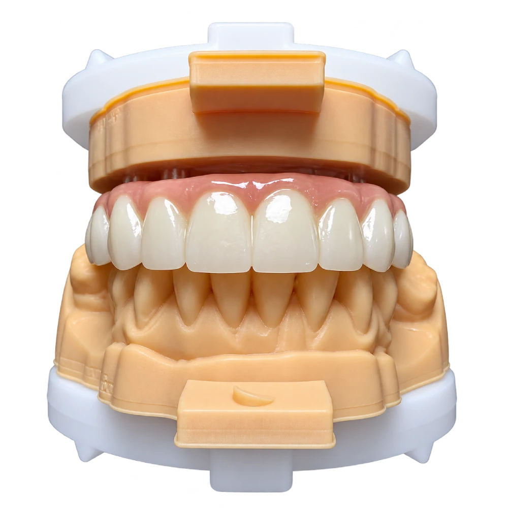
The choice of construction followed from the bruxism, not from the esthetic zone. Under repetitive functional loading, a layered design — where a veneer is built over a core — concentrates stress at the boundary between the two materials. A full-contour design removes that boundary: the restoration is a single material from the intaglio surface to the occlusal surface. That was the basis on which the construction was specified.
Esthetics were then handled inside the full-contour route rather than by adding a veneer layer: the cervical depth was matched to the adjacent natural teeth, and incisal characterisation was applied while the material was still in the green state, before sintering.
3. Anterior Zirconia Bridge Connector Design Challenges
Four units over two abutments means the entire load of the span passes through two connectors. Short clinical crowns make connector height harder to achieve, and height is the dimension that carries the bending load of the span.
So the limiting question in this case was not which zirconia, or how strong zirconia is. It was narrower and harder:
Could the connector geometry this design needs actually be produced inside the space this patient has — and can that be established før the preparation is cut?
That is the question the prescribing clinician put to us first, and it is the one we answered first.
4. What the clinician asked the laboratory for
| Requirement set by the prescribing clinician | Why it mattered in this case |
| Confirm the connector rule before the preparation was finalised | Short crowns put height at a premium; the preparation had to be planned around the achievable connector, not the other way round |
| Connector U-shaped, never V-shaped, with no sharp internal or external angles | Space was limited, so the cross-section had to be used efficiently, with transitions that avoid a stress concentration |
| Do not deepen the embrasures or thin the connector after milling | The form that leaves the mill must be the form that is seated — the delivered cross-section is what carries the load |
| Keep excursive contacts off the connector | Nocturnal loading was the dominant functional input in this case |
| Match cervical depth to the adjacent natural teeth, with incisal characterisation at the green stage, from a supplied shade and photographic reference | Esthetic zone; a single flat shade across four units would not blend |
| A cementation approach that can be reversed if required | The clinician manages caries risk on the abutments and wanted that option kept open |
| Do not compress the try-in | The connector and the marginal relationship are both still adjustable at that point, and neither is recoverable afterwards |
5. Monolithic Zirconia Bridge Design and Fabrication
Stage 1 — Design review before the preparation was confirmed.
We calculated the connector cross-section the span would need and returned that figure to the clinician før the abutments were prepared. The height target was therefore met at the preparation stage, rather than compensated for afterwards in the design software.
Stage 2 — Connector sizing, stated with its qualifiers.
A connector dimension carries no meaning on its own. The figure is set by the span, the number of abutments, the region and the material generation in use — and it is returned with those qualifiers attached, including which dimension we protect when the two compete for the space available.
For en four-unit anterior span, tandstøttede, full-contour: the connector is specified as a U-shaped cross-section with rounded transitions and no sharp internal or external anglesog height is prioritised over width.
The numeric cross-section for a given case is returned with the case, rather than published here. A figure quoted without its span, abutment count, region and material generation is not a number a preparation can be built against.
Stage 3 — CAD design.
The connector was designed U-shaped with rounded transitions and no sharp angles. Cement space was set to the instruction of the material system in use, for the bonding approach selected by the clinician. Embrasures were left at the specified depth and marked as not to be reduced after milling.
Stage 4 — Milling and sintering.
Green-state milling, with CAM scaling applied for the sintering shrinkage of the generation in use, followed by sintering on that system’s scheduled cycle with a controlled cooling profile.
Stage 5 — Shade.
Cervical depth applied to match the adjacent natural teeth; incisal characterisation carried out in the green state by infiltration staining and cutback, so the esthetic outcome does not depend on a surface veneer.
Stage 6 — Pre-dispatch check.
Before dispatch, the restoration is checked against the case sheet item by item: connector cross-section as designed, embrasures at the specified depth, occlusal contacts positioned off the connector, and marginal fit.
6. Design basis
The construction choice in this case follows published follow-up data rather than preference:
Survival reference. For tooth-supported zirconia fixed prostheses without a veneer interface, 5-year survival has been reported at 100% in a cohort with a stated follow-up period; layered designs in the same comparison were reported at 95.8% over the same period.
(Source: PMC11857140. Compare: a 12-year follow-up of layered anterior zirconia fixed dental prostheses reporting 81.5% — PubMed 33495043.)
Both figures are quoted with their design type and follow-up period, because survival figures for zirconia are not comparable across construction type, span length and follow-up length. A figure without those qualifiers is not usable — which is also why our connector standard is quoted with its qualifiers in Stage 2.
7. Try-in and follow-up
7.1 What the try-in has to establish
The try-in is the last point at which the connector height, the emergence profile and the marginal relationship can still be changed without recutting. It is checked in this order.
| # | Check | What is being established | If it does not hold |
| 1 | Seating | The restoration seats completely on both abutments, with no rock | Do not proceed. Establish what is preventing full seating |
| 2 | Marginal continuity | The margin is continuous around the full circumference of each abutment | Return to the laboratory. A discrepancy closed intra-orally cannot be corrected once the restoration is in service |
| 3 | Connector height | The connector still holds the height agreed at Stage 1, after any adjustment made at the chair | Re-evaluate against the agreed cross-section before proceeding |
| 4 | Embrasure depth | Embrasures sit at the depth specified in the design, and have not been deepened to clear a contact | Re-evaluate. A deepened embrasure changes the load path |
Two of these are not ours to close at the chair. The try-in is not the step to compress when a case is running late, and a marginal discrepancy is returned rather than resolved with cement — cement fills a gap, it does not restore a margin.
7.2 What the patient said at the interim stage
After the temporary bridge was seated, the patient’s first remark was about appearance rather than function: it looked somewhat unnatural. But the next sentence mattered more — they felt far more at ease than they had with the removable prosthesis, and when they left the chair they already considered it the right decision.
When they returned roughly two weeks later to proceed with the definitive restoration, the original objection had not come back up. The comparison they were making was not against an ideal result. It was against what they had lived with — a removable prosthesis they had been willing to decline treatment to avoid. A fixed provisional that arrived when it was promised answered that question. The shade could be refined at the definitive stage.
What had shifted was not their assessment of the appearance. What had shifted was that the thing they had been most determined to avoid — having the prosthesis come out — was no longer happening.
7.3 What is reviewed after seating
| Point | Reviewed |
| Delivery visit | Margins under direct view, occlusal contacts positioned off the connector, connector height recorded against the figure agreed at Stage 1 |
| Early review | Cervical margin integrity, plaque control at the connector embrasures, settling of the occlusal scheme |
| Periodic review | Marginal integrity, connector geometry, and any change in the functional load pattern |
For a case carrying nocturnal loading with no splint in use, the load pattern is not a fixed input. It is reviewed, not assumed.
8. Questions we are asked about this type of case
What do you need from us to start a case like this?
The span and the abutment teeth, the preparation as it will actually be cut, an occlusal record, a shade target with a photographic reference, and the material generation if one has been specified. If the preparation is not yet finalised, send the case at that point — that is exactly when the connector question can still be answered usefully (Stage 1).
How is the connector dimension decided, and will you tell us the number?
It is set from the span, the number of abutments, the region and the material generation. We give you the figure together with those qualifiers, and we state which dimension we are protecting.
How is the shade handled when the design is full-contour and there is no veneer?
Cervical depth is matched to the adjacent natural teeth, and incisal characterisation is applied in the green state before sintering. A photographic reference with the shade is what makes this reliable.
What happens if the try-in does not seat?
We want to know before the restoration goes back. Incomplete seating has a cause — contact, cement space, or a form that changed after milling — and the cause is worth identifying rather than adjusting around. The restoration is returned rather than closed with cement.
What is the turnaround, and what holds it?
It is quoted per case, from design confirmation. The clock starts when the design is confirmed — not when the case arrives — so the earliest useful moment to send a case is before the preparation is fixed, as in Stage 1.
9. Submit a Zirconia Bridge for Front Teeth Case
Send the case with the items listed in §8 and we will return the connector figure, the design rule it is based on, and the turnaround — before the preparation is finalised where the case allows it.