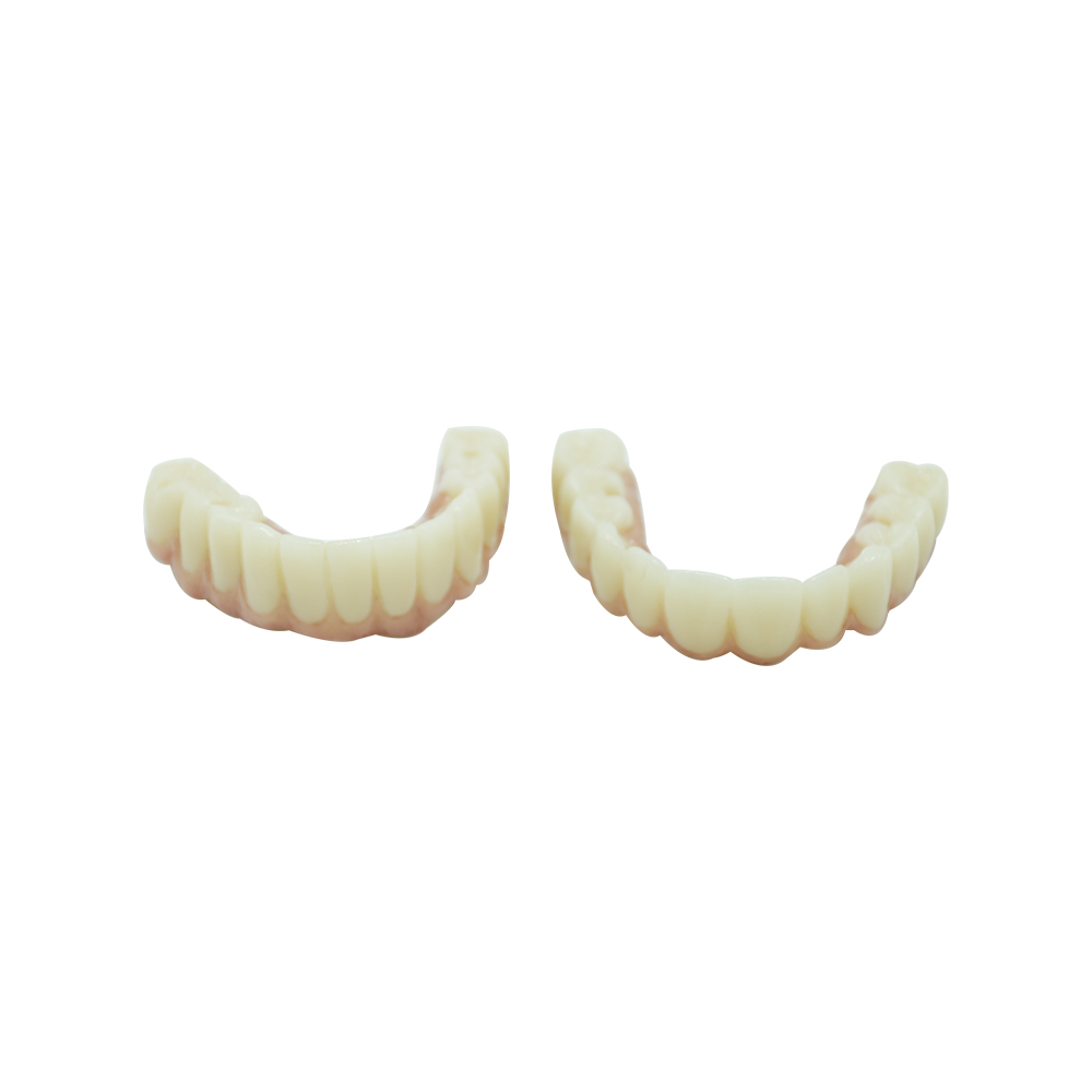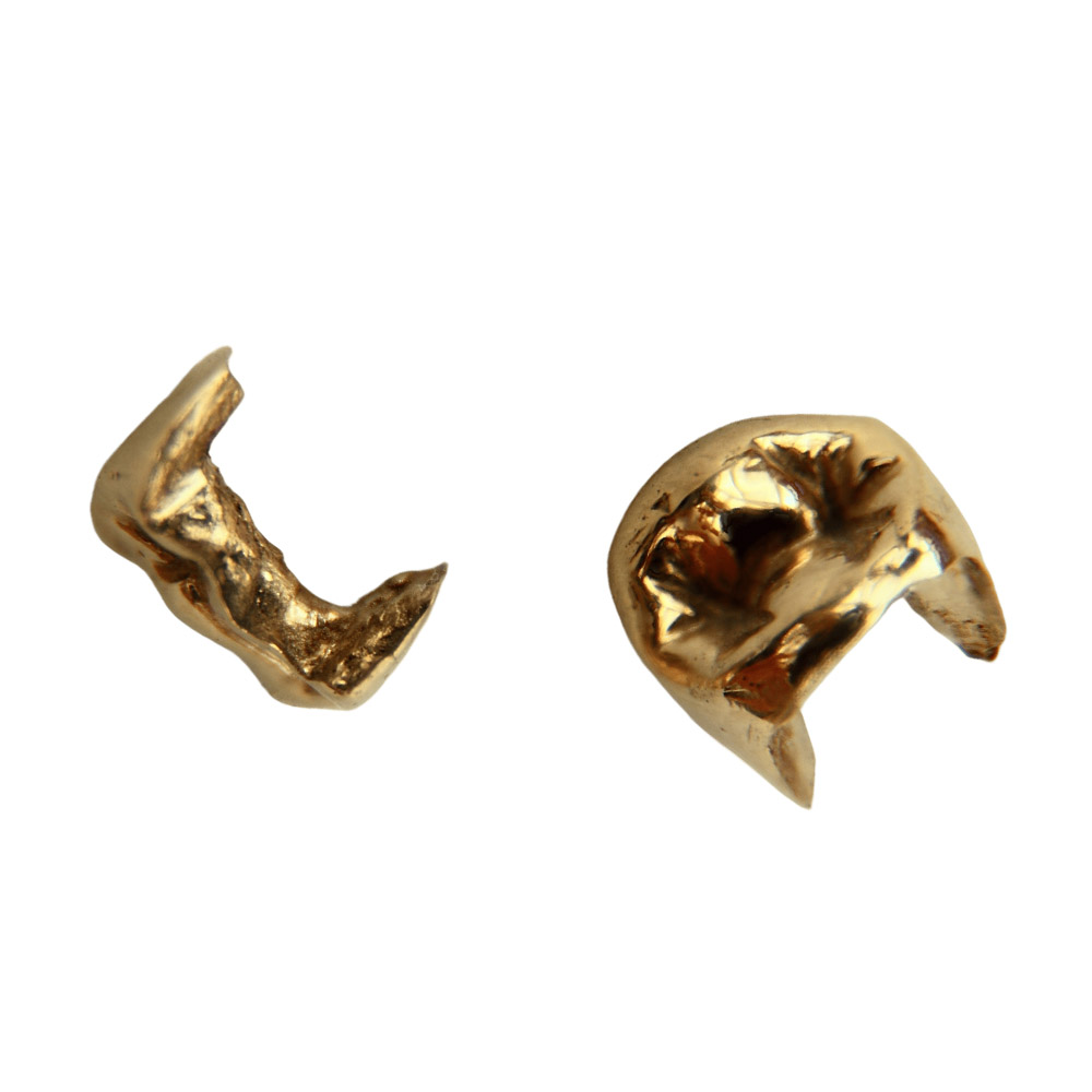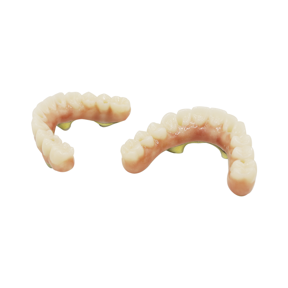
Chrome Upper Partial Denture Case Study: Bounded Posterior Saddles With a Palatal Torus
🕢 [ Попълнете формуляра и ние ще ви отговорим в рамките на 30 минути! ]
Upper right first premolar through first molar, and upper left canine through second premolar, gone in a 61-year-old. A midline palatal torus sitting exactly where the connector wanted to go, and a patient who did not want a clasp anywhere near the left canine.
Send the prescription and records → you get back the connector we intend to use, a design drawing, and a delivery date before anything is cut.
| Arch | Maxillary, Kennedy Class III mod 0, two bounded saddles |
| Alloy | Co-Cr-Mo, Co 63% / Cr 29% / Mo 6%, nickel-free, beryllium-free |
| Connector | Anterior palatal strap, routed clear of the torus |
| Ремъци | Two cast circumferential clasps, both outside the display zone |
| Framework thickness | 0.6 mm strap, thickened at the torus clearance and saddle junctions |
| Обръщане | 14 working days including one recast |
| Approval | Annotated design sent before the refractory cast was poured |
| Inspection | Three gates, released by a quality technician not involved in fabrication |
| Traceability | Case number tied to technician, machine, alloy batch and every QC entry |
Patient situation
The patient is 61, in good general health, and had been missing those teeth for four years wearing a transitional acrylic partial. The saddles were long enough that the acrylic had fractured twice at the right saddle, which is what finally brought them back.
What made this a difficult case was not the missing teeth. It was the two things standing in the way of a straightforward cast framework.
A palatal torus in the midline. The master model showed a well-defined bony protuberance on the hard palate, roughly 12 mm across and 6 mm high, sitting in the centre. A torus palatinus is a common finding and is not itself a problem — it becomes one when it sits where the major connector needs to run. On this patient the connector could not simply cross the midline, because anything passing over it would either ride up at the prominence or tip off it during insertion.
A left canine the patient would not expose. The upper left canine was being displayed on a broad smile, and the patient had already rejected one earlier design for placing a clasp on it. That tooth was the terminal abutment for the left saddle, which is precisely where retention naturally wants to sit. The dentist flagged it as a hard constraint rather than a preference.
Supporting teeth were periodontally sound and unrestored apart from existing restorations on the molars. Both saddles were bounded, with abutments on each side and no distal extension, so the load path was short and entirely tooth-supported.
What the dentist asked for
| # | Requirement | Design response required |
| 1 | No clasp on the upper left canine | Retention relocated to a molar, accepting a longer clasp span and its own trade-offs |
| 2 | Nothing crossing the torus | Connector routed anterior to the prominence, with a documented clearance dimension |
| 3 | Replace all five missing teeth and keep the option of adding #2 and #15 later | Mesh extended one tooth position beyond each saddle |
| 4 | Shade to be agreed against the remaining natural teeth | Shade photograph sent with the case, confirmed again at wax try-in |
| 5 | Fit within the existing occlusal scheme, no increase in vertical dimension | Framework thickness checked against available interocclusal space before design release |
Requirement 5 came from the dentist’s own observation that the patient’s bite was shallow posteriorly. Thicker metal there would have created an interference on closure, and the only way to solve that would have been to grind the framework after casting — which is why the clearance had to be resolved on paper.
Survey and design decisions
The first job was the survey, and on this case it changed the plan rather than confirming it.
The torus forced a rethink of the connector. With a 12 mm prominence in the midline, a conventional anterior-posterior palatal strap would have had to cross it. The path forward was a strap routed anterior to the torus, sitting in the clear palate between the torus and the anterior ridge. That keeps the connector off the bony protuberance entirely and avoids the rocking that a connector crossing a prominence tends to produce. The clearance was documented at 2 mm above the torus surface so the framework could not contact it during insertion or function.
The canine constraint forced a rethink of the retention. With the left canine excluded as a clasp site, the survey had to be re-run for usable undercuts on the left molars. There was a usable undercut on the left second molar, but it was a shallow one — about 0.25 mm — which is at the lower limit for a cast circumferential clasp. It could take a clasp, but only with a longer arm and a reciprocal arm placed carefully to keep the tooth free of unintended forces.
The dentist was told this before design release: retention would be further back, the clasp arm would be longer, and the tradeoff was a slightly less favourable lever arm on that side. That is the real cost of the aesthetic decision, and it belonged in writing rather than discovered at the fitting.
Both saddles were extended one position for later additions. The right mesh was carried onto the distal of the terminal abutment and the left mesh onto the left molar, so that if the second premolar or the canine were lost later, a tooth could be welded on and re-based without a new framework. This is cheap insurance at design stage and impossible to add later, which is why it went on the drawing with the extension marked.
Design approval before the refractory
Nothing was poured until the design came back approved. The drawing showed clasp types and locations, rest positions and dimensions, connector dimensions with the torus clearance noted, and the mesh extent including the extension positions.
Two questions went back with the design, both of them about information that was not in the data:
- Rest seat visibility. The preps on the terminal abutments were not visible on the master model. Without knowing whether a rest seat was prepared and how deep, there is no way to set rest depth or to know whether the rest will contact before the framework is fully seated. The dentist was asked to confirm which teeth were prepared and the approximate clearance.
- Interocclusal clearance confirmation. Confirmation of the available space, per requirement 5, before the 0.6 mm strap thickness was locked in.
The dentist confirmed both. Two of the rests were reclassified after the answer — one tooth had insufficient clearance to take an occlusal rest and became a guiding-plane contact instead, and the load redistributed to its neighbour.
Inside the laboratory
Duplication and blockout. The master model was duplicated in a refractory material for casting. Undercuts below the survey line were blocked out, and the model was re-surveyed to confirm the blockout had not altered the path established on the master.
Wax-up. The framework was waxed to the approved design: two circumferential clasps, rests, the anterior palatal strap cleared of the torus, and mesh over both saddles with the extension positions. The wax was checked against the drawing before it went to the refractory.
Casting. Co-Cr-Mo alloy was cast in a centrifugal casting machine. On a torus case like this, the investment and cooling schedule matters more than usual because the prominence creates a thick, uneven area that cools at a different rate from the thin strap — a differential cooling zone is exactly where porosity and distortion show up. This was the first attempt.
The problem on first cast. The first casting came out with a small porosity defect in the strap where it crossed the thicker section near the torus, visible on radiographic inspection. This was not acceptable for a load-carrying connector and was not something to be polished out or worked around.
Because the defect sat in a load path, the honest call was to recast rather than repair. It is worth being straightforward about why: welding a porosity defect in a major connector is a repair in a part that carries load from both saddles to the abutments, and the connector had to be structurally sound for the design to work. The dentist was told the same day, and the case went back for a second casting.
Second casting. The investment was re-made with attention to the cooling around the thick section. The second casting came out sound on radiographic inspection, and dimensional checks and model fit were passed.
Finishing and framework try-in. The framework was finished and returned for a try-in before the acrylic was processed. The dentist checked the seating path and stability, and confirmed there was no contact with the torus during insertion or function. No adjustments were needed on the framework itself.
Processing the base. The acrylic saddle was processed onto the mesh with mechanical retention, and the teeth were set to the shade and arrangement confirmed at the earlier wax stage.
What was delivered
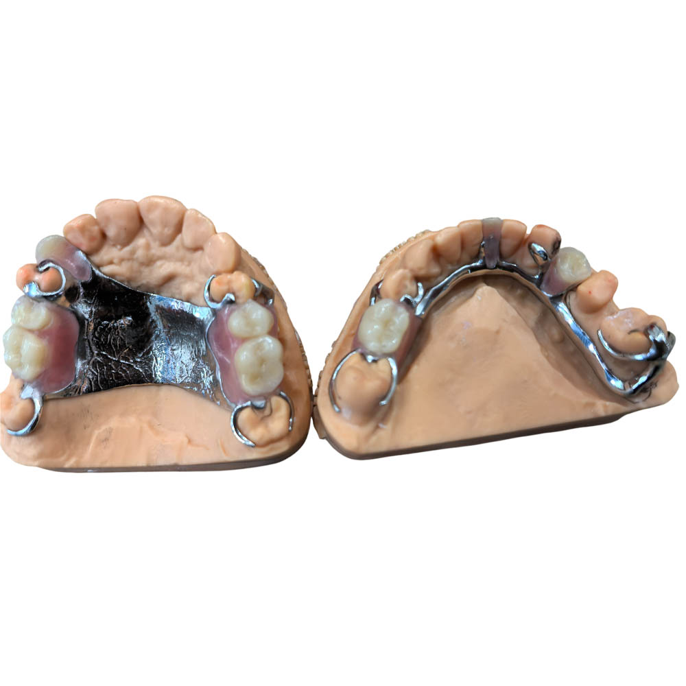
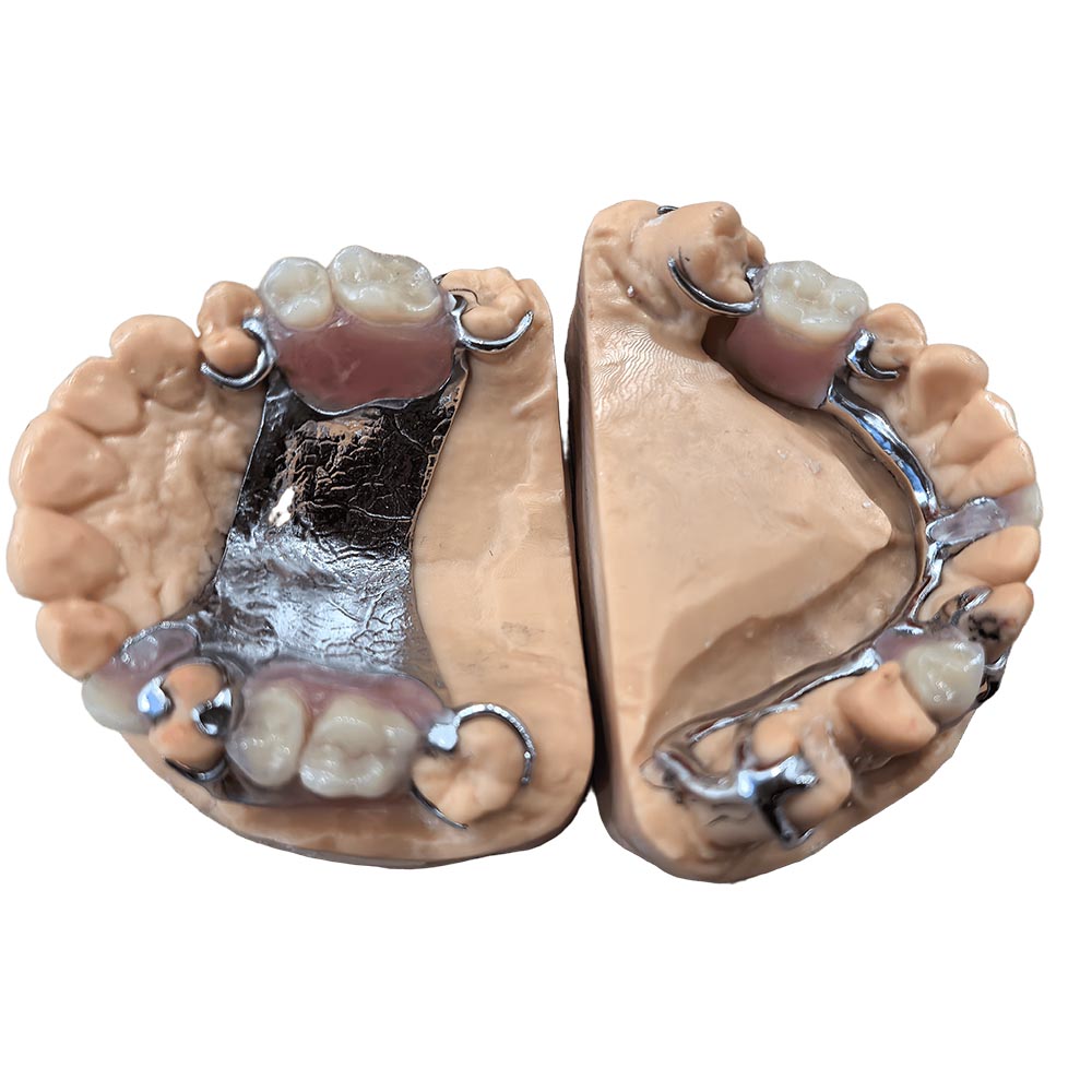
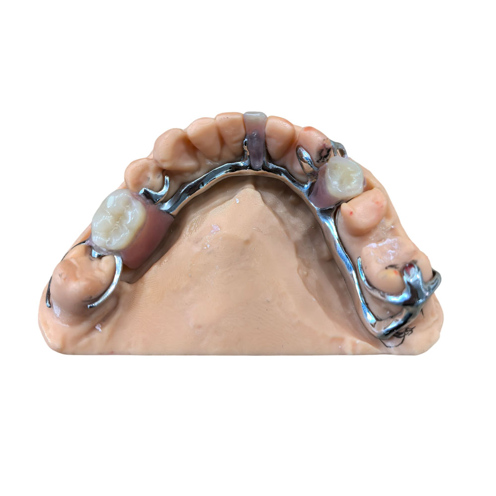
A Co-Cr-Mo framework, recast once, on an anterior palatal strap with 2 mm clearance over the torus, two cast circumferential clasps — left second molar and right first molar — both outside the display zone, no component on the left canine, and mesh extended one position beyond each saddle.
The framework seated fully at try-in with no rocking and no torus contact. The dentist adjusted the acrylic base at the chair, which is normal on a bounded saddle of that width.
Inspection record. Three gates before packing: an intake and records check, an in-process check between stages, and a final check by a quality technician who released it. Framework metal was checked for porosity, cracks and distortion by visual and magnification inspection, radiography and dye penetrant as needed, plus dimensional checks and a model fit. Clasps, rests and connectors were checked under magnification on a mounted model for form, elasticity, rest fit and connector section, confirming a smooth seating path with no rocking and no occlusal interference. Alloy for this case was Co 63% / Cr 29% / Mo 6%, nickel-free and beryllium-free. The case number ties to the technician, the machine, the alloy batch and each QC entry.
Questions that come up on cases like this
How do you handle a palatal torus?
Measure it, route the connector around it, and document the clearance. A torus is only a problem when a connector crosses it, and that is a decision rather than a fixed constraint. We do not thin a connector over a prominence to force it through — that trades a structural problem for a fracture risk. For how the connector options are weighed, see our chromium cobalt denture page.
Does a torus stop you using a palatal plate?
It depends on the size and position. A small torus can often be covered. A prominent one in the midline pushes you toward an anterior or anteroposterior strap routed clear of it. Either way the clearance gets checked against the model before the design is released.
What happens when a casting comes out defective?
It is judged by where the defect sits, not by how it looks. A surface porosity on a saddle margin can often be finished out; a defect inside a load-carrying connector cannot. Recasting costs days and the dentist hears about it immediately. Welding instead would be faster and we would rather not, because the connector is the one part that makes the whole design work.
Can a clasp be kept off a tooth the patient shows when smiling?
Sometimes, and the survey decides it. The question is whether a usable undercut exists further back. Where it does, the clasp moves and you accept a longer arm; where it does not, the constraint and the alternatives get discussed before production rather than at the fitting, because a visible clasp cannot be added to a cast framework without rebuilding it.
Is it worth extending the mesh for teeth that may not be lost?
On a bounded saddle, extending the mesh one position costs nothing at design stage and gives you a weld-and-rebase option instead of a new framework. We mark the extension on the drawing so it is a conscious decision rather than an accident.
Do you need a try-in of the framework before the base goes on?
We send the framework for clinical try-in before processing the acrylic on any case where the design depends on a specific path or on components in a sensitive area. It costs a visit and it catches seating problems while they are still cheap to fix.
What is included in turnaround?
Working days from the point where the complete records and the design approval are both in hand. Approval waiting and missing records are not counted, and the clock restarts when the missing item arrives. Shipping sits outside lab time. A recast, as on this case, extends the schedule because the second casting is a new cycle.
Can I see the inspection records?
Yes, and photos can be sent before dispatch if you want them. The final release is separate from fabrication, so the technician who builds the frame is not the one who signs the finished metal off. Radiography and dye penetrant get used where porosity, cracks or distortion need confirming rather than relying on the eye alone.
What if the shade or arrangement is not right?
Rework reasons are confirmed with you first. Free rework covers factory-side defects on removable work — a base that does not seat, a lifted edge, clasp positioning that does not function, an inaccurate bite, shade we did not hit. Not covered: a change requested after production, a different shade or material chosen after approval, or a case where the impression or scan was inadequate, we flagged it before starting, and you asked for it built anyway.
Can I set my own acceptance criteria?
Yes. Send them in writing with the case and they are locked at design approval and inspected against. They still have to sit within material and safety limits, and anything not stated before production is not treated as an acceptance standard.
Send the case and we will come back with the connector we intend to use, the design drawing, a delivery date, and anything we need from you before production starts.